What is a TALQ Functional Test
A TALQ Functional Test case is a set of easy-to-understand tests that products from TALQ members can run using the TALQ Certification Tool and that customers (cities, utilities) can refer to in their tender document.
The goal of the TALQ functional test cases is to help customers write their tenders and easily understand the capabilities of the product on the market.
Starting with version 2.6.0 of the protocol, the TALQ-certified products’ Capability Lists published on the TALQ website include the complete list of functional test cases supported by each product.
Cities and utilities should include in their tenders the list of functional tests required for their specific needs. The tables below provide the complete list of functional test cases.
List of functional test cases for Gateways
| ID | Name | Description |
|---|---|---|
| CONFIG-1 | Connect to CMS and announce light point control capabilities | The Gateway successfully connects to a CMS and transmits its capabilities (i.e. supported features) for light point configuration, control, programming and monitoring. |
| CONFIG-2 | Connect to CMS and announce cabinet control capabilities | The Gateway successfully connects to a CMS and transmits its capabilities (i.e. supported features) for lighting cabinet controller configuration, control, programming, and monitoring. |
| CONFIG-3 | Connect to CMS and announce dynamic sensor-based lighting capabilities | The Gateway successfully connects to a CMS and transmits its capabilities (i.e. supported features) for dynamic lighting based on sensor. |
| CONFIG-4 | Announce the list of light point controllers on the network | The Gateway transmits all the devices (light point controllers, cabinet controller and any other type of device) that are known on the network, to the CMS together with their configuration and asset information. |
| CONFIG-5 | Configure light point controllers electrical alarm thresholds from the CMS | The Gateway can receive the electrical alarm thresholds from the CMS and assign them to selected light point controllers. This includes Lamp Voltage Too High/Low, Lamp Current Too High/Low, Active Power Too High/Low and Power Factor Too Low. |
| CONFIG-6 | Configure the cabinet controllers alarm thresholds from the CMS | The Gateway can receive the electrical alarm thresholds from the CMS and assign them to selected cabinet controllers. |
| CONFIG-7 | Configure the light point controllers’ parameters from the CMS | The Gateway can receive configuration parameters from the CMS and assign them to selected light point controllers. |
| CONFIG-8 | Create and change group of light point controllers from the CMS | The Gateway can handle a command from the CMS to create or to change a group of light point controllers to assign them a control program. |
| CONFIG-9 | Change the sampling frequency for telemetry measurements | The Gateway can change the sampling of telemetry measurements on light point controllers and cabinet controllers and properly reflected in the next data log sent to the CMS. |
| CONFIG-10 | Change the reporting frequency for telemetry measurements | The Gateway can change the reporting frequency, i.e. how often it sends data logs to the CMS, for telemetry measurements on light point controllers. |
| CONFIG-11 | Update the firmware of the physical devices | The Gateway supports data package service and accepts a data package to update firmware on a physical device such as a light point controller. |
| ID | Name | Description |
|---|---|---|
| MONITOR-1 | Report basic electrical values to the CMS | The Gateway measures mains voltage, current, active power, and power factor, and sends these values to the CMS via the data-logging service. |
| MONITOR-2 | Report cumulative energy usage (kWh) | The Gateway sends the total energy used as a cumulative counter (kWh) to the CMS via the data-logging service. |
| MONITOR-3 | Report lamp operating hours (runtime) | The Gateway reports each lamp’s total hours of operation as a cumulative counter to the CMS via the data-logging service. |
| MONITOR-4 | Report lamp switch-on count | The Gateway reports how many times each lamp has been switched on, as a cumulative counter to the CMS via the data-logging service. |
| MONITOR-5 | Report power loss count | The Gateway reports the total number of power interruptions detected for each lamp as a cumulative counter to the CMS via the data-logging service. |
| MONITOR-6 | Confirm dimming level after manual override command | When a manual override is sent (e.g., set dimming level to X%), the Gateway forwards the command to the device and confirms, via on-demand request and data-logging service, that the actual dimming level matches (or closely follows) the requested level. |
| MONITOR-7 | (deleted) | |
| MONITOR-8 | Report temperature values | The Gateway sends temperature measurements from connected devices or sensors to the CMS via the data-logging service. |
| MONITOR-9 | Report presence detection | The Gateway sends presence events or values from sensors to the CMS via the data-logging service. |
| MONITOR-10 | Report ambient noise level | The Gateway sends noise level values to the CMS via the data-logging service. |
| MONITOR-11 | Report dimming levels | The Gateway sends dimming level values to the CMS via the data-logging service. |
| MONITOR-12 | Report firmware update status and progress | The Gateway reports firmware update events (start, progress, completion or failure) to the CMS. |
| ID | Name | Description |
|---|---|---|
| CONTROL-1 | Manually set a single light point | The Gateway accepts a manual override command from the CMS (e.g., set dimming level or switch ON/OFF) and applies it to one specific light point. |
| CONTROL-2 | Manually set the dimming level on a group of light points | The Gateway accepts a manual override command from the CMS and applies it to a defined group of light points. |
| CONTROL-3 | Manually set the dimming level on a single light point with a delay | The Gateway accepts a manual override command from the CMS that includes a delay (e.g., “in 10 minutes”) and applies the change to one light point at the requested time. |
| CONTROL-4 | Manually change dimming level with a smooth ramp | The Gateway accepts a manual override command from the CMS that includes a ramp-up/ramp-down time and adjusts the dimming level on one light point smoothly to the requested level. |
| CONTROL-5 | Switch a light automatically using a photocell | The Gateway runs a local control program that turns a single light point ON and OFF based on the status of a local photocell. |
| CONTROL-6 | Adjust dimming level on presence detection | The Gateway runs a local control program that raises or lowers the dimming level of a single light point when a presence sensor is triggered. |
| CONTROL-7 | Adjust dimming level on noise detection | The Gateway runs a local control program that changes the dimming level of a single point when a noise sensor is triggered. |
| ID | Name | Description |
|---|---|---|
| ALARM-1 | Detect and report lighting alarms | The Gateway detects lighting-related issues (e.g., lamp/driver issues, high temperature) and send alarms to the CMS via the data-logging service. |
| ALARM-2 | Detect and report electrical alarms | The Gateway detects electrical issues (e.g., over/under-voltage, over-current, power loss) and sends alarms to the CMS via the data-logging service. |
| ALARM-3 | Report invalid schedules or control programs | If a calendar or control program is missing, invalid, or inconsistent, the Gateway raises an alarm and sends it to the CMS via the data-logging service. |
| ALARM-4 | Report sensor-activity events | When activity is detected by local sensors (e.g., presence or noise), the Gateway sends an event to the CMS via the data-logging service. |
| ALARM-5 | Provide alarm status on request | When the CMS asks for it, the Gateway returns the actual status of the alarms (e.g., active/inactive). |
| ID | Name | Description |
|---|---|---|
| PROGRAM-1 | Run a daily fixed time on/off and dimming schedule | The Gateway receives a schedule that turns a light point ON/OFF and sets dimming level at specific times, the same every day of the year. |
| PROGRAM-2 | Run an astro-clock on/off schedule with fixed-time dimming (daily) | The Gateway switches a light point ON/OFF at sunrise/sunset with an adjustable time offset (± minutes) and applies a time-based dimming plan during the astro-clock active period, every night. |
| PROGRAM-3 | Run a photocell-based on/off schedule with fixed-time dimming (daily) | The Gateway turns a light point ON when the photocell indicates darkness and OFF when it is bright and follows a time-based dimming plan during the photocell’s active period, every night. |
| PROGRAM-4 | Combine photocell and astro-clock switching with fixed-time dimming (daily) | The Gateway turns a light point ON/OFF based on whichever trigger happens first, photocell darkness/brightness or astro sunrise/sunset with offset and follows a time-based dimming plan during the active period, every night. |
| PROGRAM-5 | Run an OFF period that crosses midnight (or midday) | The Gateway turns lights OFF for a time window that crosses midnight (or midday). When the schedule resumes, the lights return to the last scheduled dimming level. |
| PROGRAM-6 | Support special date ranges (seasonal exceptions) | The Gateway handles calendars with a year-round default rule plus a higher-priority rule that applies between two dates (e.g., Sept 10-Oct 16). |
| PROGRAM-7 | Support weekly exceptions (e.g., weekends) | The Gateway handles calendars with a year-round default rule plus a higher-priority rule that applies on specific weekdays (e.g., every Saturday and Sunday). |
| PROGRAM-8 | Support combined weekly and seasonal exceptions with priorities | The Gateway handles layered calendars: a year-round default rule; a higher-priority weekend rule (e.g., every Sat/Sun); an even higher-priority rule for a special period (Day 1–Day 2); and, within that period, a highest-priority rule for specific days (e.g., Saturdays). The most specific rule takes precedence. |
| PROGRAM-9 | Run a sensor-based dynamic lighting control program | The Gateway executes a control program that changes dimming level based on sensor detection (e.g., presence). |
List of functional test cases for CMS
| ID | Name | Description |
|---|---|---|
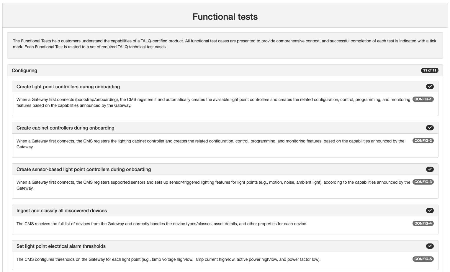
| CONFIG-1 | Create light point controllers during onboarding | When a Gateway first connects (bootstrap/onboarding), the CMS registers it and automatically creates the available light point controllers and creates the related configuration, control, programming, and monitoring features based on the capabilities announced by the Gateway. |
| CONFIG-2 | Create cabinet controllers during onboarding | When a Gateway first connects, the CMS registers the lighting cabinet controller and creates the related configuration, control, programming, and monitoring features, based on the capabilities announced by the Gateway. |
| CONFIG-3 | Create sensor-based light point controllers during onboarding | When a Gateway first connects, the CMS registers supported sensors and sets up sensor-triggered lighting features for light points (e.g., motion, noise, ambient light), according to the capabilities announced by the Gateway. |
| CONFIG-4 | Ingest and classify all discovered devices | The CMS receives the full list of devices from the Gateway and correctly handles the device types/classes, asset details, and other properties for each device. |
| CONFIG-5 | Set light point electrical alarm thresholds | The CMS configures thresholds on the Gateway for each light point (e.g., lamp voltage high/low, lamp current high/low, active power high/low, and power factor low). |
| CONFIG-6 | Set cabinet controller alarm thresholds | The CMS configures electrical alarm thresholds on the Gateway for cabinet controllers. |
| CONFIG-7 | Set and update light point parameters | The CMS sends light point configuration parameters to the Gateway (e.g., identifiers, location/asset details, nominal power, and other device settings) and can modify them later. |
| CONFIG-8 | Create and manage groups of light points | The CMS creates and edits groups of light points (e.g., by street, zone, or project) and sends the group definitions to the Gateway for use in control and reporting. |
| CONFIG-9 | Configure sampling frequency for measurements | The CMS sets how often the Gateway reads measurements on the devices and/or sensors. |
| CONFIG-10 | Configure reporting frequency to the CMS | The CMS sets how often the Gateway sends measurement readings to the CMS (independent of the sampling frequency). |
| CONFIG-11 | Deploy firmware updates to field devices | The CMS sends a firmware package to the Gateway, which then updates the target device(s) and reports status about devices’ firmware update and progress back to the CMS. |
| ID | Name | Description |
|---|---|---|
| MONITOR-1 | Receive and handle basic electrical values | The CMS receives mains voltage, current, active power, and power factor from the Gateway via the data-logging service and handles them correctly. |
| MONITOR-2 | Track cumulative energy (kWh) | The CMS receives the cumulative energy counter (kWh) from the Gateway via the data-logging service and handles it correctly. |
| MONITOR-3 | Track lamp operating hours | The CMS receives each lamp’s total runtime as a cumulative counter from the Gateway and handles it correctly. |
| MONITOR-4 | Track lamp switch-on count | The CMS receives the cumulative switch-on counter for each lamp from the Gateway and handles it correctly. |
| MONITOR-5 | Track power loss count | The CMS receives the cumulative count of power interruptions from the Gateway and handles it correctly. |
| MONITOR-6 | Verify dimming level after a manual override | The CMS sends a manual override command to a light point and, after a configurable delay, uses on-demand reads to confirm the reported dimming level approaches the requested level. |
| MONITOR-7 | (deleted) | |
| MONITOR-8 | Receive and handle temperature | The CMS receives temperature values from the Gateway via the data-logging service and handles them correctly. |
| MONITOR-9 | Receive and handle presence detection | The CMS receives presence events/values from the Gateway via the data-logging service and handles them correctly. |
| MONITOR-10 | Receive and handle ambient noise level | The CMS receives noise-level values from the Gateway via the data-logging service and handles them correctly. |
| MONITOR-11 | Receive and handle ambient light level (lux) | The CMS receives light-level values from the Gateway via the data-logging service and handles them correctly. |
| MONITOR-12 | Track firmware update status and progress | The CMS receives firmware update events (start, progress, completion/failure) from the Gateway and presents them correctly. |
| ID | Name | Description |
|---|---|---|
| CONTROL-1 | Manually send an override command to a single light point | The CMS sends a manual override (ON/OF or dimming level) to one light point. |
| CONTROL-2 | Manually send an override command to a group of light points | The CMS sends a manual override command to a defined group of light points. |
| CONTROL-3 | Schedule a manual override command with a delay | The CMS sends a manual override command to one light point with a delay before execution. |
| CONTROL-4 | Manually change the dimming level with a smooth ramp | The CMS sends a manual override command to one light point that includes a ramp-up/ramp-down time. |
| CONTROL-5 | Deploy a photocell-based on/off control program (single light point) | The CMS creates and sends a control program that turns a single light point ON/OFF based on a local photocell. |
| CONTROL-6 | Deploy a presence-based dimming control program (single light point) | The CMS creates and sends a control program that changes the dimming level of a single light point based on a local presence sensor. |
| CONTROL-7 | Deploy a noise-based dimming control program (single light point) | The CMS creates and sends a control program that changes the dimming level of a single light point based on a local noise sensor. |
| ID | Name | Description |
|---|---|---|
| ALARM-1 | Handle lighting alarms | The CMS ingests and processes lighting-related alarms sent by the Gateway via the data-logger service. |
| ALARM-2 | Handle electrical alarms | The CMS ingests and processes electrical alarms sent by the Gateway via the data-logger service. |
| ALARM-3 | Handle invalid schedule/program alarms | The CMS ingests and processes alarms about invalid calendars or control programs sent by the Gateway via the data-logger service. |
| ALARM-4 | Handle sensor-activity events | The CMS ingests and processes activity events (e.g., presence/noise) sent by the Gateway via the data-logging service. |
| ALARM-5 | Request and handle current alarm status | The CMS requests the status of alarms from the Gateway and handles the response correctly. |
| ID | Name | Description |
|---|---|---|
| PROGRAM-1 | Create and deploy a daily fixed time on/off and dimming schedule | The CMS generates and sends a control program that turns a light point ON/OFF and sets dimming level at specific times, the same every day. |
| PROGRAM-2 | Create and deploy an astro-clock on/off schedule with fixed time dimming | The CMS generates and sends a control program that switches a light point at sunrise/sunset with an adjustable time offset (± minutes) and applies a time-based dimming plan during the astro-clock active period, every day. |
| PROGRAM-3 | Create and deploy a photocell-based on/off schedule with fixed-time dimming | The CMS generates and sends a control program that turns a light point ON when the photocell indicates darkness and OFF when it is bright, with time-based dimming during the photocell active period, every day. |
| PROGRAM-4 | Create and deploy a combined photocell + astro-clock schedule with fixed-time dimming | The CMS generates and sends a control program that turns a light point ON/OFF based on whichever trigger occurs first, photocell darkness/brightness or astro sunrise/sunset with time offset, and applies time-based dimming during the active period, every day. |
| PROGRAM-5 | Create and deploy an OFF window that spans the day boundary | The CMS generates and sends a control program that turns a light point OFF for a defined time window that crosses the day boundary (e.g., 23:00–04:00 when the system’s day boundary is midnight, or a window that crosses 12:00 if the boundary is noon). Outside this window, the light follows its normal schedule. |
| PROGRAM-6 | Support seasonal exceptions (date-range rules) | The CMS generates and sends a calendar with a year-round default rule plus a higher-priority rule that applies between two dates (e.g., Sept 10–Oct 16). |
| PROGRAM-7 | Support weekly exceptions (e.g., weekends) | The CMS generates and sends a calendar with a year-round default rule plus a higher-priority rule for specific weekdays (e.g., every Saturday and Sunday). |
| PROGRAM-8 | Support layered weekly + seasonal exceptions (priority order) | The CMS generates and sends a layered calendar: a year-round default rule; a higher-priority weekend rule; and an even higher-priority rule for a special date range (e.g., Day 1-Day 2, including Saturdays within that period). The most specific rule takes precedence. |
| PROGRAM-9 | Create and deploy a sensor-based dynamic lighting control program | The CMS generates and sends a control program that changes dimming level based on sensor detection (e.g., presence), then returns to the normal level after the configured timeout. |